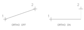
 Most regular AutoCAD users will know that the F8 key toggles the ORTHO mode, which constrains cursor movement horizontal and vertical to the current UCS. There are also 2 types of tracking we can use to allow us to draw quickly and accurately, object snap tracking and polar tracking. POLAR, ORTHO, OSNAP, and OTRACK are all selectable toggles in the status bar, normally found at the bottom of the AutoCAD environment.
 OTRACK allows tracking along alignment paths based on other OSNAP points. F11 switches it on and off. When active, OSNAP tracking allows you to project from an acquired OSNAP, the cursor follows along a dotted line that represents the ortho extension. By default, the tracking is orthogonal only; it can be modified on the Polar Tracking tab of drafting settings, DSETTINGS. Note: for OTRACK to work, there need to be running OSNAPS on (AUTOSNAP).
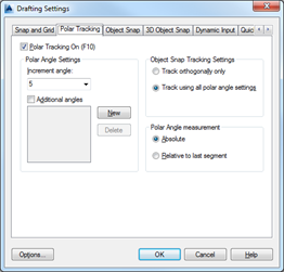
POLAR tracking allows tracking along any defined polar angle tracking path from any point, no OSNAP is required. F10 switches it on and off. The angles evaluated for the POLAR is defined in the Drafting Settings, Polar Tracking Dialog box, too. Both settings' state is visible on the status bar at the bottom of the AutoCAD main window.
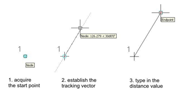 As an example, let’s draw a line at an angle of 30 degrees from a selected start point at a length of 200 units.
First, turn POLAR on (F10), and set the increment angle to 30 or to a divisor of 30 (5, 10, 15) in the Polar Tracking tab. Now, start the LINE command, and select your start point. As you drag your cursor alone paths that are along the angular increments, the POLAR tracking vector will appear. Once that is highlighted, you can simply type in the distance value (200) and AutoCAD will draw the line at the specified length along the POLAR tracking angle selected.
Here is a second example, drawing a line from a known point to a point orthogonal to two existing corner points. First start the LINE command, and OSNAP the upper right intersection of the lower object.
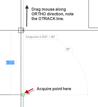 With ORTHO and OTRACK on, drag your mouse vertically, you should see a faint green dashed line representing the ortho extension from your selected point stretching upwards. This symbol means the otrack has established the vertical lORTHO from the corner as a potential OTRACK. Next, hover your crosshairs on the second object corner, but do not left-click! We are simply using the corner to establish the OTRACK line. Instead, drag your crosshairs horizontally; you should see the faint green dashed line extend horizontally as you move.
 When you get to the point where the vertical and horizontal extensions meet, both green dashed lines appear, as shown in the image to the right. Click when both green dashed lines appear, now, and the line endpoint will be at the projected extensions intersection.

That's a simple example of how OTRACK can help you acquire locations or situations with no geometry in the desired location. Of course, there are lots of other possibilities, too.
Feel free to share your POLAR and OTRACK usage experiences!


